Showing posts with label teardown. Show all posts

Sunday, February 8, 2015

Lidl PIR nightlight teardown and hack

Summary: I picked up some low cost (E8) battery powered / PIR triggered nightlights that were on sale in Lidl. The heart of the device is a common PIR IC. One of the IC pins can be tapped to drive digital IO line for occupancy detection or an intruder alarm. Given that PIR sensors alone in small volumes can often exceed €10/$10 this represents good value for money.

The device (Livarno Lux brand (Lidl), model Z31685C)  comprises 8 white LEDs, a  PIR (Pyroelectric Infrared) sensor with a polyethylene plastic fresnel lens [1] and a photodiode (which suppresses the illumination of the LEDs during the day). It is powered by 8 x AAA alkaline cells (supplied) arranged in two sets of 4 in series.

The device can be mounted on a wall or ceiling by attaching a mounting plate with screws or an adhesive strip (also supplied).

Teardown:

The top cover comes off easily enough: seems to be held on by friction alone. Then an aluminiumized plastic reflector can be pulled of revealing a single sided PCB secured to the base with three screws. On the top surface of the PCB is the PIR sensor, a light sensing photodiode and two electrolytic caps.

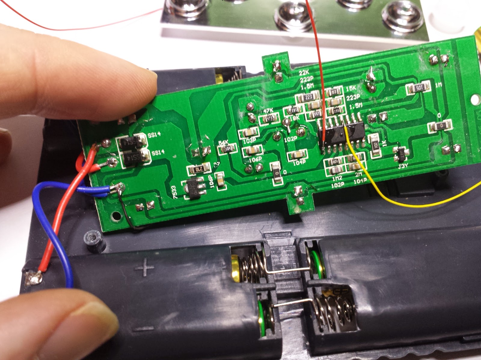
Underside of nighlight PCB.
 (the thin red and yellow wires soldered to the main IC were
added by myself to facilitate interfacing with MCU).
Click to expand image.
The fun is on the underside. At the heart is a 16 pin PIR IC marked "HS0001". Googling this didn't yield any useful results, but I found several PIR ICs that had similar marking codes: LP0001 [3] and BISS0001 [4]. The datasheets for these have a reference design which look very similar to the layout of this PCB. After some probing, I can say with certainty that the HS0001 used on this board is functionally identical to the LP0001 and BISS0001.

The board is powered by the two parallel banks of 4 x AAA alkaline cells. Each bank supplies approx 5.5V. A diode in series with each bank prevents one bank from driving the other in reverse (which can cause alkaline cells to leak). A linear regulator provides a 3.3V rail to the PIR IC.
Reference design schematic from LP0001 datasheet.


Most of the passive components on the board are resistors and capacitors used to set various tunable parameters of this IC [list pins]

The VO (pin 2) line from the IC drives the gate of a (FET?) transistor which switches the lighting LEDs (driven by the 5.5V direct from the batteries).

So how power efficient is this? Using a little hack I measured the quiescent current at about 90uA and the current with LEDs on at 70mA. Unfortunately the supplied AAA cells don't have any product code, but typically AAA alkaline cells have capacities in the range from 800 - 1200 mAh. Let's say 1000mAh. And as there is two sets in parallel that's a total of 2000mAh capacity. If you assuming the LEDs are never triggered, that's an approximate battery lifetime of 2000mAh/90uA = 22222 hours or 2.5 years. In reality if the LEDs are on at least a few minutes a day so that brings the battery lifetime down to under a year.

Driving a MCU

So can this cheap nightlight be used as a PIR sensor for another application? 
So this is what the OUT2 (output of second stage opamp) pin of the PIR IC looks like on an oscilloscope when I walk into the room (about half way though the trace).  So it seems OUT2 tends to about half the supply voltage (1.6V) when there is no activity. Then when a person enters its field of view OUT2 oscillates between 0 and 3.3V.  So if you connect this directly to a digital IO input, all you need to do is detect a transition (high to low or low to high). Apply classic switch debounce logic (except on a multisecond time scale) and you have a occupancy / intruder detection mechanism!

To facilitate my hack, I soldered some think (30AWG) wire to OUT2 , GND / battern -ve and the 3.3V rail (to draw power for my MCU application).


Oscilloscope trace from the OUT2 pin showing a person enter the room at about the half way mark.

Conclusion:

If you can find these in Lidl (it's a very hit and miss thing with them) this can be converted into a nice neat PIR sensor for less money than ordering a dedicated PIR sensor [2]. Plus you get the LED night light functionality and 8 AAA alkaline cells!

References:

[1] Focusing devices for pyroelectric infrared sensors
http://www.glolab.com/focusdevices/focus.html

[2] Adafruit PIR (motion) sensor  ($10)
http://www.adafruit.com/products/189

[3] LP0001 datasheet
http://akizukidenshi.com/download/ds/sctech/LP0001.pdf

[4] BISS0001 datasheet
http://www.seeedstudio.com/wiki/images/2/2f/Twig_-_BISS0001.pdf


Friday, August 2, 2013

Silvercrest (Lidl) TwinTalker 4810 446MHz PMR radio teardown

I picked up these  "Silvercrest" (Lidl) brand TwinTalker 4810 446MHz PMR (private mobile radio) which are on special at Lidl right now. ("Silvercrest" is a Lidl own brand,  Topcom is the manufacturer of this device).


This PMR set peaked my interest because of the external mic/headphone socket. I have the idea that perhaps these could be adapted to packet radio without any need to hack the hardware (I find these radios handy on occasion, so I'd prefer to also keep them functional as walkie-talkies).

There was a time when devices like this came with full schematics and a service manual. Sadly, nowadays, you have to figure out everything for yourself (unless someone else already has!).

Opening it doesn't take much effort. Two screws in the battery compartment and two screws covered by rubber bungs near the top.


The first thing I noticed was the 56 pin SOIC IC at the bottom of the board. This is a Matsushita AN29160AA transceiver chip which deals with most of the radio protocols details. Excerpt from the datasheet:

"AN29160AA is IC for Transceiver. One package involve four systems about IF, PLL, Regulator, and AF. Involving 1st IFamp, 2nd Mixer, 2nd IFamp, FM-Detector, 460MHz PLL, Regulator for RXRF/ TXRF/ VCO/ MCU, OPAMPs for filter and Speaker Amplifier."


Also on that side of the PCB is a Z324 quad low power op-amps IC,  and a 2kBit K24C02C serial EEPROM which I guess is used to preserve radio settings across power cycles. The radio module and RF power amp is in a metal can along the edge of the PCB (bottom of photo above).

To view the underside of the PCB, I found that I needed to remove a blob of glue which fixed the helical antenna to the case. I was then able to pry up the PCB enough to take photos. (To remove it fully I would have had to snip the speaker wires, and I wasn't bothered enough to do that).

On the underside there is the LCD in a metal case. I assume the MCU is also in that area. There are pads for the user interface rubber buttons. Next to the button pads is a test pad which could be used to solder a breakout wire. As I want to keep this functional, I'm not going to tear down any further... besides from experience, there isn't much that can be done with the MCUs on consumer devices. The test pad labeled "TX MOD" does make me curious though...

Best I can tell the CFWM 450HT is related to driving the peizzo speaker. Next to that a crystal can marked 21.7 (MHz?). The marking on the speaker is "JW 16Ω 0.5W".


The supplied headphones use a 3 pole 2.5mm audio plug and comprise a single ear piece and a pod with a mic/push-to-talk button.


Best I can tell so far: the plug tip is for the mic and push-to-talk switch and floats at about 2.4V, the middle ring of the plug is audio out for the ear piece. When no transmission is received it's at 0V, when a transmission is received it jumps to 2.2V with the audio signal superimposed. Last ring is ground.

Measuring the resistance of the mic line of the headset to ground I see that the resistance is 3k when the PTT switch is open and drops to 1.1k when the PTT switch is pressed/closed.


Update (1 Aug 2014): I got back to looking at interfacing this PMR to a microcontroller and took another look at the headset interface (the 3 pole 2.5mm jack socket at the top).  I shall refer to the 3 lines as Tip, Middle and Sleeve.  I still haven't figured it all out yet, but these are various measurements I've taken while the headset is connected.

  • Tip-Sleeve resistance with PTT switch off: 2.9k
  • Tip-Sleeve resistance with PTT switch pressed (on): 1k
  • Middle-Sleeve resistance: 36 ohms (PTT switch has no effect)
  • Tip-Middle resistance with PTT switch off: 2.8k
  • Tip-Middle resistance with PTT switch pressed (on): 1.1k
  • Voltage of Tip relative to Sleeve with PTT switch off: 2.45V
  • Voltage of Tip relative to Sleeve with PTT switch on: 1.25V
  • Voltage of Middle relative to Sleeve with nothing being received: 0V
  • Voltage of Middle relative to Sleeve when receiving: 2.0V with audio out overlayed.

I also verified that shorting Tip to Sleeve via a 1.8k resistor will cause the unit to 'key up' and transmit (this was done with the headset disconnected). I found that the value of resistor is important. a 1k would cause the unit to only key up momentarily: the 1k resistor caused the Tip voltage to drop to about 0.9V which I guess is too low.

Here is scope trace from Middle (relative to Sleeve) when I key up and release. The waveform is the end-of-transmission bleep.


So in summary:

  • Sleeve is ground.
  • I can detect if there is an incoming signal by looking at the Middle DC offset. A value of about 2.5V indicates reception in progress. The AC part of the Middle is the received audio. Audio peak-to-peak voltage is about 1.5V at full volume.
  • I can cause the unit to transmit by dropping the Tip voltage to about 1.25V (eg shorting through a 1.8k resistor)
  • Still to do: interfacing a MCU DAC output to the audio in.
I'll update as I find out more.


Sunday, July 28, 2013

Silvercrest (Lidl) EIM-804 'digital weekly timer' teardown

I purchased up a few Silvercrest brand EIM-804 'digital weekly timer'  from Lidl two years, with some sort of hackery in mind. And finally I found a use for one. So I tore one apart.


There are two PCBs: one on the bottom which deals with power related matters and one attached to the top lid which is the user interface (UI). The PCBs are connected with a 3 wire ribbon cable.

The power board comprises a fuse, mains relay, relay drive circuit and a low voltage (1.2V) power supply and backup battery (cell) for the user interface board.


The UI board comprises an application specific Chip-on-Board (COB) IC, a custom LCD mated to the PCB by a zebra strip and contact pads for rubber buttons. It's connected to the power PCB by a 3 wire ribbon cable. Two wires for power (1.2V) and one (labeled 'D' on the PCB) for relay control. I found if this was left floating the relay was on and if I drive it to 0V the relay was switched off.


There isn't much that can be done with the UI board and the application I have in mind will require a separate MCU to control the relay. So I unsoldered the ribbon cable from it.

I am hoping to use the low voltage power supply to power my application. So I took a shot at reverse engineering the schematics of the power board:


So it seems there are two DC power rails: a 24V rail set by zener diode DZ1 (a 24V 1N4749A) which together with Q1 is used to energize the relay coil. A second power rail is derived from the 24V rail and is set by DZ2 and provides 1.2V for the UI PCB and the 1.2V backup battery.

The relay is controlled by line D. It's interesting to note that the Q1 (a SS9014 NPN) is a high gain transistor, so it doesn't take much base current to cause the relay to activate.  If D is left to float then the small current that flows through R4 (about 73µA) is enough to activate the relay. If D is driven to 0V then that current is directed away from Q1 causing the relay to deactivate.

D2 is the usual fly-back diode which absorbs the voltage spike due to the sudden interruption of current through the relay coil. Diode D1 protects Q1 (and the driving logic) from excessive current if D line is high.

The purpose of D3 (I guess) is to prevent the 1.2V battery from draining through EC2 etc when the device is unplugged.

One important observation about the 1.2V low voltage rail: the 0V is not ground. It will vary between 0V and +24V relative to the ground/neutral line. Therefore you must optoisolate it if interfacing to external circuitry. The following is a scope trace from the 1.2V line on the ribbon cable. Connecting this to external (grounded) logic devices is likely to damage it.


So my plan is to use this device with the UI PCB removed and a Lite-On LTV-817S opto-isolator with the output connected to the D and 0V line of the ribbon cable. The relay will be on by default. Passing a current through the isolator's input LED will cause the relay to switch off.  More on this another time...


Wednesday, October 31, 2012

Philips CFL bulb tear down

I experienced a rare CFL bulb failure last night (I've got about 16 bulbs installed about 12 years ago. This has been the third failure to date). For the past few weeks this bulb was taking longer than normal to ramp up to full brightness, so I suspect a tube failure.

I couldn't resist having a quick peek inside the blown bulb. I opened by prying with a large flat head screwdriver:


This is the electronics board:


Nothing exciting: a transformer, 5.6uF 360V capacitor (the large can on top), 2 x ST 13003A NPN power transistors and a hand full of miscellaneous discretes.

And the tube:


Disclaimer: Don't try this if you don't know what you're doing. There is a trace amount of mercury (toxic!) inside the tube and you can injure yourself on the glass if you break it. Dispose correctly according to local regulations afterwards.

Saturday, June 30, 2012

OKI 900 mobile phone limited tear down

I found my old OKI 900 analog mobile phone while looking for a ferrite rod in a junk box at my parents home. This unit was manufactured in 1991. I acquired it second-hand around 1993. It cost me about a months wages back then.

Googling this phone, it seems to have been a very hackable phone back in it's day. It's based on the 8051 MCU core and there are various ROMs available on the network to do all sorts of interesting things.  However, right now I don't have any interest/time in making any mods to this. Indeed I couldn't even be bothered powering it up. So I'll take Dave Jones advice: "don't power it up, take it apart"... but only out of lazyiness :-)


Saturday, May 12, 2012

Lidl 'Silvercrest' radio teardown

Last week Lidl (a German budget supermarket chain) had a small "transistor" radio on special. Like a lot of their low end electronics it was "Silvercrest" brand. For various reasons I had need of one (actually I was planning to canabilise it for its ferrite rod antenna, but found an alternative source in the mean time).

Usually Lidl stuff is fine. Not brands you'd normally recognize, but solid stuff none-the-less. So this was rather disappointing.
On powering up, the LCD was faulty. The top half of the display wasn't working.

So I had a look inside:


Apart from the grubby PCB (normal enough for low end electronics these days) there was a botched bodge capacitor (not connect on the left terminal) and a wire to the ferrite antenna nicked by a screw.

So I exchanged it for another. But thankfully decided to checked it out in the car before leaving. Radio #2 didn't even power up. So I tried #3 which did work fine. Two out of three failure rate seems a bit high... or maybe I was just unlucky.

The IC in the photo is a Sony CXA1691 AM/FM radio chip. Everything else looked like it was lifted right out of the 1970s. But hey, it's just a "transistor" radio...