Monday, May 31, 2010

Using an Arduino as a simple logic analyzer (part 3)

In my previous two posts on this topic I outlined how a Arduino could be used to snoop on a I2C bus with the aim of enhancing a HL168Y blood pressure monitor.  Part 1 was about recording logic levels, part 2 interpreted those levels into I2C signals (START, STOP, data). Those signals where hand interpreted to reverse engineer the memory map.

In this post I'll go one step further and automatically interpret the bus signals into memory read and write operations and output to the serial port.

Fortunately the HL168Y reads and writes to the EEPROM one byte at a time (the EEPROM supports page read/write which would complicate matters). The output format is one operation per line:
"R aaa vv" or "W aaa vv", where R indicates a read operation and W a write operation. The second parameter "aaa" is the memory location in hex (from 000 to 3fff) and "vv" is the 8 bit value in hex read from / written to the memory location.

On taking a blood pressure measurement the following bus activity was observed after the reading as complete:

W 010 05
W 011 1e
W 012 86
W 013 28
W 014 10
W 015 11
W 016 82
W 017 44

Referring to the record format in part 2, that's month 5, day of month 0x1e (ie 30),  hour is 6 with the PM flag on (ie 6pm), minutes 0x28 (40) and BP 111 / 82 with heart rate of 0x44 (68).

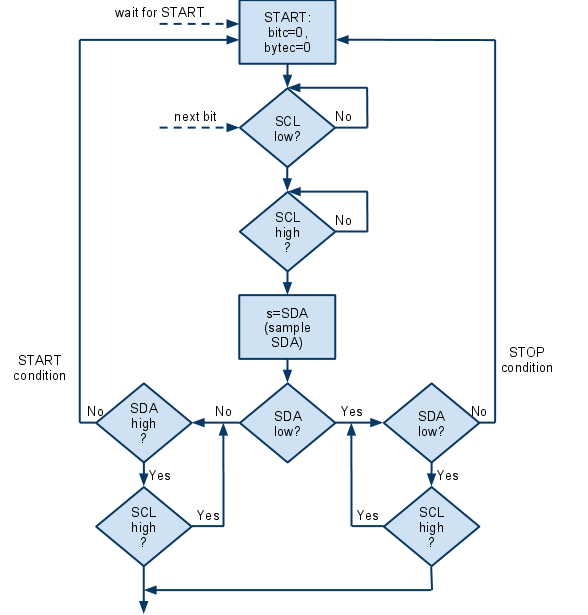
Signals to Read/Write flowchart


Signals to Read/Write Arduino C/C++ program

/**
 * I2C bus snooper. Written to eavesdrop on MCU to EEPROM 
 * communications in a HL168Y blood pressure monitor. SCL 
 * is connected to Arduino pin 2 and SDA to pin 3.
 * This version will decode read and write operations to 
 * EEPROM outputting to serial port as
 * "R aaa vv" or "W aaa vv" records (one per line) where
 * aaa is 10 address bits as hex digits and vv is value as
 * hex digits.
 */

int SCL = 2;
int SDA = 3;

char hexval[16] = {'0', '1', '2', '3', '4', '5', '6', '7', '8', '9', 'a', 'b', 'c', 'd', 'e', 'f'};

#define LOG_SIZE 255
unsigned char datalog[LOG_SIZE];
unsigned char logptr;

void setup()   {                
  pinMode(SCL, INPUT);  
  pinMode(SDA, INPUT); 
  Serial.begin(115200);
}

void loop()                     
{
  unsigned char s, b, byteCounter, bitCounter, rwFlag;
  unsigned char addr_hi, addr_lo;
  unsigned int t = 0;
  
  logptr = 0;
  
  waitForStart:
 
   // Expect both SLC and SDA to be high
  while ( (PIND & 0b00001100) != 0b00001100) ;
  // both SLC and SDA high at this point
  
  // Looking for START condition. Ie SDA transitioning from 
  // high to low while SLC is high.
  while ( (PIND & 0b00001100) != 0b00000100) {
    if ( (--t == 0) &&  (logptr > 0) ) {
      writeData();
    }
  }
  
  firstBit:
  
  byteCounter = 0;
  bitCounter = 0;
  
  nextBit:
 
  // If SCL high, wait for SCL low
  while ( (PIND & 0b00000100) != 0) ;
    
  // Wait for SCL to transition high. Nothing of interest happens when SCL is low.
  while ( (PIND & 0b00000100) == 0) ;
    
  // Sample SDA at the SCL low->high transition point. Don't know yet if this is a
  // data bit or a STOP or START condition.
  s = PIND & 0b00001000;
    
  // Wait for SCL to transition low while monitoring SDA for a transition.
  // No transition means we have data or ACK bit (sample in 's'). A hight to
  // low SDA = START, a low to high SDA transition = STOP.
  if (s == 0) {
    // loop while SCL high and SDA low
    while ( (PIND & 0b00001100) == 0b00000100) ;
    if ( (PIND & 0b00001100) == 0b00001100) {
         // STOP condition detected
         if (logptr > LOG_SIZE - 20) {
           writeData();
         }
         goto waitForStart;
    }
  } else {
    // loop while SCL high and SDA high
    while ( (PIND & 0b00001100) == 0b00001100) ;
    if ( (PIND & 0b00001100) == 0b00000100) {
        // START condition.
        goto firstBit;
    }
  }
  
  // OK. This is a data bit.
  bitCounter++;
  
  if (bitCounter < 9) {    
    b <<= 1;
    // if data bit is '1' set it in LSB position (will default to 0 after the shift op)
    if (s != 0) {
      b |= 0b00000001;
    }
    
    goto nextBit;
  }
  
  // 9th bit (ack/noack)
  
  bitCounter = 0;
  byteCounter++;
  
  switch (byteCounter) {
    case 1: // 1010AAAW where AAA upper 3 bits of address, W = 0 for writer, 1 for read
    if ( (b & 0b11110000) != 0b10100000) {
      goto waitForStart;
    }
    // Set A9,A8 bits of address
    addr_hi = (b>>1) & 0b00000011;
    rwFlag = b & 0b00000001;
    break;
    
    case 2: // data if rwFlag==1 else lower 8 bits of address
    if (rwFlag == 1) {
      // data read from eeprom. Expect this to be the last byte before P
      //datalog[logptr++] = ' ';
      datalog[logptr++] = 'R';
      datalog[logptr++] = ' ';
      datalog[logptr++] = hexval[addr_hi];
      datalog[logptr++] = hexval[addr_lo>>4];
      datalog[logptr++] = hexval[addr_lo & 0b00001111];
      datalog[logptr++] = ' ';
      datalog[logptr++] = hexval[b >> 4];
      datalog[logptr++] = hexval[b & 0b00001111];
      datalog[logptr++] = '\n';
    } else {
      addr_lo = b;
    }
    break;
   
    case 3: // only have 3rd byte if rwFlag==0. This will be the data.
    if (rwFlag == 0) {
      //datalog[logptr++] = ' ';
      datalog[logptr++] = 'W';
      datalog[logptr++] = ' ';
      datalog[logptr++] = hexval[addr_hi];
      datalog[logptr++] = hexval[addr_lo>>4];
      datalog[logptr++] = hexval[addr_lo & 0b00001111];
      datalog[logptr++] = ' ';
      datalog[logptr++] = hexval[b>>4];
      datalog[logptr++] = hexval[b & 0b00001111];
      datalog[logptr++] = '\n';
      
      if (logptr > LOG_SIZE - 10) {
        writeData();
      }
      
      break;
    }
    
  } // end switch
 
  goto nextBit;
  
}

void writeData () {
  for (int i = 0; i < logptr; i++) {
    Serial.print(datalog[i]);
    datalog[i] = 0;
  }
  logptr=0;
  Serial.println ("\n");
}

Converting read/writes operations into BP measurement records

I wrote a small JSP script to make the conversion.

<%
 String SEP = "\t";
 if ( request.getMethod().equals("GET") ) { 
%>
<form method="POST">
<textarea name="data" rows="20" cols="40"></textarea>
<br />
<input type="submit" value="Submit" /></form>
<%
 } else {
  
  response.setContentType("text/plain");
  
  int[][] records = new int[40][8];
  String[] lines = request.getParameter("data").split("\r\n");
  for (String line : lines) {
   if ( ! (line.startsWith("R") || line.startsWith("W"))) {
    continue;
   }
   String[] p = line.split(" ");
   int addr = Integer.parseInt(p[1],16);
   int value = Integer.parseInt(p[2],16);
   // Addresses under 16 are not for BP readings
   if (addr < 16) {
    continue;
   }
   int recordIndex = (addr - 16)/8;
   int col = addr%8;
   records[recordIndex][col] = value;
  }
  
  for (int i = 0; i < 40; i++) {
   if (records[i][0] == 0) {
    continue;
   }
   
   // European format
   //out.write (records[i][1] + "/" + records[i][0] + "/2010 ");
   
   // US/spreadsheet format
   out.write (records[i][0] + "/" + records[i][1] + "/2010 ");
   
   // Hours
   // Stored in 12 hour clock value (lower nibble) and bit 7 = PM flag.
   int h = records[i][2];
   h =  h > 127  ?  (h & 0xf) + 12 : (h & 0xf);
   
   if (h < 10) {
    out.write ("0");
   }
   out.write (h + ":");
   
   // Minutes
   int m = records[i][3];
   if (m < 10) {
    out.write ("0");
   }
   out.write ("" + m + SEP);
   
   // Systolic
   int sys = ((records[i][4] & 0xf0)>>4) * 100;
   sys +=  ((records[i][5] & 0xf0)>>4) * 10;
   sys +=  ((records[i][5] & 0x0f));
   out.write ("" + sys + SEP);
   
   // Diastolic
   int dia =  (records[i][4] & 0x0f) * 100;
   dia +=  ((records[i][6] & 0xf0)>>4) * 10;
   dia +=  ((records[i][6] & 0x0f));
   out.write ("" + dia + SEP);
   
   // Heart rate
   out.write ("" + records[i][7]);
   out.write ("\n");
  }
 }
%>

Running this with the write records above results in the following BP record:
5/30/2010 18:40 111 82 68

I've chosen US date format as this works best with spreadsheets.

Thursday, May 27, 2010

Comments on the HTC Desire

A few people have asked me about my opinion of the HTC Desire. I'm not going to do a thorough review: there are thousands of them out there. Instead here is a few short note of things I have noticed myself.

Some background: I purchased my first Android phone – a HTC Magic – in June 2009 at full SIM-free price (€450 I recall) and I've been delighted with that phone for the most part. As I was due an upgrade from Vodafone and the HTC Desire became available earlier this month at a subsidized price (€170 + €40 x 18 month contract -- it's €500 contract free) I decide to go for that.

The good

This sure is a sexy phone. The HTC Sense UI which is a layer on top of the underlying Android OS is visually appealing. Having said that I think I'd still prefer the plain old (relatively) boring Google UI. I guess companies need to "differentiate" their products, to the Sense UI is important to HTC.

The screen size is larger than that of the Magic, making typing the screen keyboard marginally more accurate. It's still a pain, especially in portrait orientation. In landscape typing works very well.

Screen technology is AMOLED (Active Matrix Organic LED) -- not LCD. Really vivid colors. Deep blacks.

It's fast and responsive (having a 1GHz Snapdragon ARM processor). Plenty of RAM (about 512MB).

The not-so-good

No traditional red hangup button. If there two things every phone must be able to reliably do is:

1. Make an emergency call (but only when you intend to)
2. Hang up reliably.

Instead you have a red screen button. That's if you're lucky enough to have the dialpad in the foreground. If not you're screwed. It's far too easy to fat finger an unintended call while messing with the contacts list. By the time you navigate to the hangup function the person at the other end has already answered, and you're faced with the age old dilemma: do you apologize or just hang up. I opt for latter, especially at 4am :-)

The AMOLED display is great, but not perfect. Because of the way LCD works it's still possible to read text in direct sunlight. Nothing is visible on AMOLED under the same conditions. So if you have to use a phone outdoors in a sunny climate an LCD based phone might be a better choice.

It has got the new micro-USB connector, so my stock of mini-USB cables is no good for this phone. For me cables are like pens -- I like to have a few in every room. Micro-USB is the universal charger standard going forward, so this is a very good thing in the long run.

Camera is 8 mega pixels 5 mega pixels. But if ever I needed a lesson why mega-pixels are meaningless unless you have the optics to back it up this is it. See photo. Still, it's not bad for casual use.

Conclusion

Would I recommend this phone? For sure. Right now it's probably the best Android phone available in Ireland. The recently announced Android Froyo software update adds plenty of speed and some amazing new features (eg tethering and phone-as-hotspot support). Desire users can expect an over the air update to Froyo later this year. How does it compare with an iPhone? I don't know– I never used an iPhone and probably never will. Many experts believe that Froyo running on decent hardware like the Desire beats the socks off iPhone. I would be inclined to agree.

Update (27 May 2010) - Camera was incorrectly stated to be 8 mega pixels. It's in fact 5 mega pixels.

Tuesday, May 25, 2010

Using an Arduino Duemilanove as a quick and dandy logic analyzer (part 2)

I've updated my Arduino logic analyzer code to interpret I2C bus signals. My intention is to eavesdrop on write operations to the EEPROM of the Health & Life Co HL168Y Blood Pressure Monitor so that readings can be stored and downloaded automatically to a PC.

The HL168Y uses a ST Microelectronics M24C08 8 kbit (1 kbyte)  serial EEPROM which uses I2C for communications. I2C is a inter-chip communications protocol that requires just two lines (clock and data). The details of the EEPROM I2C communications protocol is beyond the scope of this post, but in essence a memory write operation comprises a START (S) condition followed by 3 x 9 bit bytes (8 data, 1 acknowledgment bit) followed by a STOP (P) condition. First byte is a chip address + two MSB of memory address + R/W bit, second byte is the lower 8 bits of the memory address, and last byte is the content to be written to memory.

The following bus activity was recorded after a blood pressure reading 132 (systolic mmHg), 78 (diastolic mmHg), 86 bpm heart rate at 22:21 on 24 May.

S 1010 0000 0 0000 0111 0 0000 0010 0 P into 0x007 write 0x02 - record counter (this was reading #2)
S 1010 0000 0 0001 1000 0 0000 0101 0 P into 0x018 write 0x05 (5 dec) - month of year
S 1010 0000 0 0001 1001 0 0001 1000 0 P into 0x019 write 0x18 (24 dec) - day of month
S 1010 0000 0 0001 1010 0 1000 1010 0 P into 0x01a write 0x0c - bit7 pm flag, bit3-0 hours (12 hour clock)
S 1010 0000 0 0001 1011 0 0001 0101 0 P into 0x01b write 0x15 (21 dec)  - minutes
S 1010 0000 0 0001 1100 0 0001 0000 0 P into 0x01c write 0x10 - bits7-4: sys decimal digit 2
S 1010 0000 0 0001 1101 0 0011 0010 0 P into 0x01d write 0x32 - bits7-4: sys digit 1,0 (hex as dec)
S 1010 0000 0 0001 1110 0 0111 1000 0 P into 0x01e write 0x78  - dia (hex as dec)
S 1010 0000 0 0001 1111 0 0101 0110 0 P into 0x01f write 0x56 (86) - bpm
S 1010 0000 0 0000 1111 0 0101 0000 0 P into 0x00f write 0x50 (80)

(abbreviations: sys - systolic pressure in mmHg; dia - diastolic pressure in mmHg, bpm - heart rate in beats per minute)

While month, day of month, minutes and heart rate are stored as one would expect (unsigned 8 bit integer), other values are stored a little strangely. The hour of day is stored in 12 hour clock with the MSB indicating AM/PM (1 indicating PM). Bits 3-0 are the 12 hour clock hour.

Blood pressure is also stored in an strange format: the upper nibble of byte 4 is the hundreds digit of systolic pressure. I'm guessing the lower nibble is the hundreds digit of the diastolic pressure (thankfully I can't put that to the test :-). Byte 5 upper nibble is the tens digit of systolic and byte 5 lower nibble is the units digit of systolic. Byte 6 upper nybble is the tens digit of diastolic and byte 5 lower nibble is the units digit of diastolic.

The following program will listen to the I2C bus and gather data in a buffer until MAX_EVENTS events have been recorded at which time it will dump all to the serial port. There is no timeout in this version. The single BP reading was not sufficient to fill the buffer, so it's necessary to press the "Memory" button on the device once or twice to cause enough bus activity to fill the buffer and flush the data.

/**
 * I2C bus snooper. Written to eavesdrop on MCU to EEPROM 
 * communications in a HL168Y blood pressure monitor. SCL 
 * is connected to Arduino pin 2 and SDA to pin 3.
 */
#define MAX_EVENTS 512
int SCL = 2;
int SDA = 3;

char data[MAX_EVENTS];
int dp = 0;

void setup()   {                
  pinMode(SCL, INPUT);  
  pinMode(SDA, INPUT); 
  Serial.begin(115200);
}

void loop()                     
{
  unsigned char s;
  dp = 0;
  
   lookForStart:
   
   // Expect both SCL and SDA to be high
  while ( (PIND & 0b00001100) != 0b00001100) ;
  // both SLC and SDA high at this point
  
  // Looking for START condition. Ie SDA transitioning from 
  // high to low while SLC is high.
  while ( (PIND & 0b00001100) != 0b00000100) ;
  data[dp++] = 'S'; 
   // wait for SCL low
  while ( (PIND & 0b00000100) != 0) ;
  
  lookForData:
  
  while (dp < MAX_EVENTS) {
    
     // wait for SCL low
    while ( (PIND & 0b00000100) != 0) ;
    
    // Wait for SCL to transition high
    while ( (PIND & 0b00000100) == 0) ;
    
    // Sample SDA at the transition point
    s = PIND & 0b00001000;
    data[dp++] = (s == 0 ? '0' : '1');
    
    // Wait for SCL to transition low while looking 
    // for start or stop condition. A START or STOP
    // means the previous bit isn't a data bit. So will
    // write START, STOP condition into the same memory slot
    if (s == 0) {
      while ( (PIND & 0b00000100) != 0) {
        if ( (PIND & 0b00001000) != 0) {
           // detected STOP condition
           data[dp-1] = 'P';
           goto lookForStart;
        }
      }
    } else {
      while ( (PIND & 0b00000100) != 0) {
        if ( (PIND & 0b00001000) == 0) {
           // detected START condition
           data[dp-1] = 'S';
           goto lookForData;
        }
      }
    }
  }
  // have exceed storage. Dump to serial port and restart.
  writeData(); 
}

void writeData () {
  int i;
  for (i = 0; i < dp; i++) {
    Serial.print (data[i]);
    if (data[i] == 'P') {
      Serial.println ("");
    }
  }
  Serial.println ("");
}

Sunday, May 23, 2010

Using an Arduino Duemilanove as a quick and dandy logic analyzer

Update (20 Oct 2010): Fixed error in code (due to last minute editing of the code MAX_BITS used in a loop should have been changed to MAX_TRANS). Code has now been updated.

I am attempting to snoop and decode the communication on an I2C bus with the intention of intercepting read/write operations to an EEPROM chip.

I've ordered a Bus Pirate to help, but it won't be here for at least a week. In the mean time I've put my Arduino Duemilanove on the job. I've written a short program that polls the IO pins in a tight loop looking for state changes and recording the state and the time of the transition.

I've opted to store the data in RAM and then dump to serial port at the end of the capture period. Most Duemilanoves come with a ATMega 328 chip which has 2KByte of RAM: enough to capture about 500 transitions. Streaming data to the serial port probably won't work as the pins can't be monitored while data is being transmitted on the serial port resulting in missed transitions. [Update: (25 May 2010)  This may be possible after all as the ATMega chip has a hardware UART.]

Plotting the data

The program will record all pins of the ATMega Port D (Arduino Duemilanove pins 0 to 7).  I'm monitoring two lines: the I2C SCL (clock) and SDA (data) where are connected to pins 2 and 3 of the Arduino respectively.

Data output is obtained from the Serial Monitor and  looks like this:

42778 0 0 0 0 1 1 0 0
42779 0 0 0 0 1 0 0 0
42789 0 0 0 0 1 0 0 0
42790 0 0 0 0 1 1 0 0
42798 0 0 0 0 1 1 0 0
42799 0 0 0 0 0 1 0 0
42816 0 0 0 0 0 1 0 0
42817 0 0 0 0 0 0 0 0
42861 0 0 0 0 0 0 0 0
42862 0 0 0 0 1 0 0 0
42880 0 0 0 0 1 0 0 0

First column is the time stamp. Subsequent columns are pin 7 to pin 0 state.

Gnuplot is a simple to use plotting package that gets results quickly. Cut/paste the output from the serial monitor into a file (eg la.dat). The following command will port pin 4 (SDA) an pin 3 (SCL). I've multiplied the SCL line by 2 so that the two traces are clearly visible.

plot 'la.dat' using 1:6 with lines, 'la.dat' using 1:($7 * 1.2 - 0.1) with lines;


The Arduino program

#define MAX_TRANS 256

char data[MAX_TRANS];
short data_t[MAX_TRANS];

int dp = 0;

void setup()   { 
  DDRD = 0b00000000; // (pins 0 - 7 on Duemilanove) as input
  Serial.begin(115200); // serial port at decent high speed
}

void loop()                     
{
  dp = 0;
  char d, pd;
  pd = PIND & 0b0001100 ;  // only interested in pins 2,3
  unsigned short t = 0, pt;
  
  // Poll port in tight loop. Use iteration counter as timer.
  while (dp < MAX_TRANS) {
    t++;
    d = PIND & 0b0001100; // only interested in pins 2,3
    if (d == pd) {
      continue;
    }
    data[dp] = d;
    pd = d;
    data_t[dp] = t - pt;
    pt = t;
    dp++;
  }

  // Write data to serial port
  int i;
  long tt=0;
  for (i = 1; i < dp; i++) {  
    tt += data_t[i];
    writeData(tt-1, data[i-1]);
    writeData(tt, data[i]);
  }

}

void writeData (unsigned short t, unsigned char data) {
    Serial.print (t);
    for (int i = 0; i < 8; i++) {
      Serial.print (  (data & 0b10000000) == 0 ? " 0" : " 1");
      data<<=1;
    }
    Serial.println ("");
}

Monday, May 17, 2010

How to make an Ambulatory Blood Pressure Monitor (ABPM) for just €20 ($25)


Fig 1: Modified HL168Y wrist cuff blood pressure monitor.
Summary: this post explains how to convert a Health & Life Co. HL168Y blood pressure monitor (sold by Maplin for €17) into an ambulatory blood pressure monitor using nothing but a few components costing no more than €3. Basic knowledge of electronics, simple tools and a PIC microcontroller programmer are required. The modification was successfully tested and a chart of the data is presented at the bottom of this post.

Blood pressure (BP) is notoriously difficult to measure. A single reading at a doctor’s surgery can be misleading as BP varies throughout the day and is often biased due to anxiety ("white coat hypertension"). For a better picture an ambulatory blood pressure monitor (ABPM) is used. This is an unobtrusive device that automatically takes readings at fixed intervals, usually 20 minute intervals during the day and 1 hour intervals at night. The data is stored on the device and is transferred to a computer at the end of the measuring period.

ABPMs are generally made for the medical profession and cost in excess of €1K. As far as I tell there are just a few key features that differentiate ABPMs from the cheap consumer models that can cost as little as €17:
  1. Automatically take measurements
  2. Transfer data to computer
  3. Unobtrusive and robust
  4. Calibrated and certified
So I started thinking: how easy would it be to modify a cheap consumer BP monitor to have ABPM functionality? Maplin sell a HL168Y cuff device for €17. At that price I thought it was worth a shot. The worst that can happen is I’m left with €17 of e-junk.
Disclaimer: Do not try this with a BP monitor that you need for medical purposes. Modifications will almost certainly void your warranty and may affect the accuracy and performance of the device. If you want to tinker with your BP monitor I recommend buying one specifically for this purpose. Also do not use the data obtained for any serious medical decisions: it's of unknown quality.


Fig 2: Innards of the HL168Y BPM
Most electronic BPMs use oscillometric measurement. A cuff which is wrapped around the arm (at wrist or upper arm level) is inflated to about 200mmHg (26kPa) pressure. At this pressure the cuff is sufficiently constrictive to block blood circulation to the arm. A pressure sensor monitors the pressure in the cuff. In addition to measuring the absolute pressure in the cuff, this sensor sufficiently sensitive to ‘hear’ the characteristic pulsations of the heart (which are manifested as small variations in pressure).

At 200mmHg blood flow is constricted -- no heart beat will be detected. The cuff is slowly deflated. At the systolic pressure (around 120mmHg for most people) the heart will be able to overcome the cuff pressure. The microcontroller will be able to detect a small pulsing variations in the cuff pressure. The cuff continues to deflate until a point is reached where no heart beat is detected. This is the diastolic pressure.

It is a very simple device essentially comprising a cuff, air pump, pressure sensor. A microcontroller  coordinates these components, make the calculations and display the result. As the Maplin device has a 40 reading memory, at its simplest all that is required is a means of pressing the button automatically every 20 minutes. The readings will have to be manually transcribed into a spreadsheet or other analysis tool. In theory, this could be done mechanically (using a solenoid actuator) but would would involve a cumbersome attachment to the front face of the device – not very practical. Fortunately simulating a button press electrically is trivial.

The HL168Y device has 4 buttons: Start/Stop, Mode, Set and Memory. These are standard rubber buttons. When depressed, a conductive rubber foot on the underside of the button squeezes against interleaved copper contacts on the PCB.

On the reverse of the PCB are test pads which provide a convenient way to test or tap into important points in the device. TP4 corresponds to the Start/Stop button. Pulling this line to ground (0V) simulates pressing the button.

A microcontroller unit (MCU) like a PIC from Microchip Technology Inc. is perfect for the task. PICs are small, cheap and operate at voltages down to 2V. The HL168Y uses 3V (2 x AAA cells) so the PIC can draw power from the same battery.

My first choice was a tiny 8 pin 12F675. I figured this was small enough to fit in the spare space inside the device housing. Unfortunately I ran into some programming problems so opted for a larger 18 pin 16F627.

The Hardware


Fig 3: schematic of modification
Three points need to be tapped into:
  • Red: Battery + terminal (3V)
  • Black: Battery - terminal (0V)
  • Orange: testpad TP4 (the Start/Stop button)

Solder three wires to the above points. I strongly recommend that the wires are restrained using tape (otherwise it’s all to easy to damage the PCB by accidental tugging on the wires). These three wires connect to pins on the PIC (see fig 4).


Fig 4: The 16F627 PIC MCU mounted on an IC socket. Also underneath (not in view) 2K2 resistor linking Vdd to MCLR pin.

To facilitate easy reprogramming of the PIC I soldered a IC socket into some veroboard. The PIC can be easily mounted and removed as needed.

The red wire is connected to Vdd (pin 14), black to Vss (pin 5) and orange to PB0 (pin 6). I found that unless the master clear pin MCLR (pin 4) is tied high the device is unstable. Therefore under the board (not visible in the photo) is a 2K2 resistor linking pin 4 to pin 14 (any value 1K  - 10K will do).

Test by powering up. If all goes well the BPM should automatically start taking a reading in 5 minutes (enough time to reset the clock).  Tape the attachment to the side of the device using duct tape.  Ensure there are no lose wires that can be snagged on something as you go about your day.


The Software

The requirements for the first iteration of my modification is quite simple: Simulate "Start" being pressed sleep for 20 minutes and repeat.

Delays are often achieved by a tight loop or using internal counters. As this is a battery operated device minimizing power consumption is vital. Delays using loops or timers would push current consumption into the mA region, depleting the battery in days.

Fortunately there is a low power alternative: the PIC SLEEP instruction which puts the chip into a deep hibernate mode. The device can be woken from sleep by interrupt (eg button press) or using the device Watchdog Timer. Using the SLEEP instruction I’ve been able to reduce average power consumption into the micro-amp region.

For the first iteration of this project I've decided to use the C compiler that comes with Microchip's free MPLAB IDE. The free C compiler does not produce the most compact code, but as it's such a short program it is not a problem.

The C program below is compiled with MPLAB and the resulting HEX file uploaded onto the 16F627 chip using a Velleman K8048 PIC programmer.

#include <htc.h>

__CONFIG(INTIO & WDTEN & PWRTDIS & BORDIS & LVPEN  & UNPROTECT);

// Internal crystal frequency 4Mhz
#define _XTAL_FREQ 4000000

int loopDelay (unsigned char n);
int pauseSeconds (unsigned char n);
int pauseMinutes (unsigned char n);

void init(void) {
 PORTB = 0x00000001; // set RB0 on latch high before making pin output
 TRISB = 0b11111110; // set RB0 as output (1=input, 0=output)
}

void main(void) {
 init();
 while (1) {
  pauseMinues (5);

  // Press start button twice (once to wake, once to start)
  pressStartButton(); 
  pauseSeconds(2);
  pressStartButton();

  pauseMinutes(15);
 }
}

/** 
 * Simulate the pressing of the Start button
 */
int pressStartButton () {
 PORTB = 0b0;
 loopDelay(128);
 PORTB = 0b1;
}


/** 
 * Seep for one whole cycle of the watchdog timer (about 2s in 16F627)
 */
int wdtSleep () {
 CLRWDT();
 SLEEP();
}

/**
 * Sleep for 'n' seconds by calling wdtSleep() in a loop
 */
int pauseSeconds (unsigned char n) {
 int j;
 n /= 2;
 for (j = 0; j < n; j++) {
  wdtSleep();
 }
}

/**
 * Sleep for 'n' minutes by calling wdtSleep() in a loop
 */
int pauseMinutes (unsigned char n) {
 int i,j;
 for (j = 0; j < n; j++) {
  // about 1 minute
  for (i = 0; i < 30; i++) {
   wdtSleep();
  }
 }
}

/**
 * Cause a delay by looping. Useful for short delays, but uses considerably
 * more power than using SLEEP
 */
int loopDelay (unsigned char n) {
        unsigned char i,j;
        for (i = 0; i < n; i++) {
                CLRWDT();
                for (j = 0; j < 127; j++) {
                        NOP();
                }
        }
}

The Data

I tested this device on myself for a 30 hour continuous stretch over the weekend. It's like wearing a big heavy watch and generally was not a problem. For good readings it is necessary hold still and keep the device at heart level during the 30 seconds or so it takes to measure. It can be easily removed at any time if necessary. I was able to sleep with it (although I think it did affect the quality of my sleep).

The following is a chart of that run. It shows the expected day/night difference, with a noticeable dip during the peak of the sleep cycle at about 04:00.


Limitations

The main problem with this that it starts automatically and continues to trigger a measurement every 20 minutes while batteries are in the device. The only way to turn it off is to remove the battery (which by the way also erases the clock and memory). Also we have to manually key the data from the screen into our spreadsheet / analysis software. This is a major pain point for which I no solution yet. I would also very much like to be able to fit this modification inside the original housing.

Finally a wrist cuff device is not the best for ABPM because readings should be taken while the wrist is at heart height. Any higher or lower will bias the reading. An upper arm cuff is far more preferable as it's always (approx) at heart level and is more comfortable to wear. It may be possible to modify this device into such a configuration, although it will involve tearing it apart.

Phase 2 will attempt to address some of these shortcomings.